This is the third installment in our CPU design series. In Part 1, we covered computer architecture and how a processor works from a high level. The second part took a look at how some of the individual components of a chip were designed and implemented. Part 3 goes a step further to see how architectural and schematic designs are turned into physical chips.
How do you transform a pile of sand into an advanced processor? Let's find out.
(instruction set architectures, caching, pipelines, hyperthreading)
Part 2: CPU Design Process
(schematics, transistors, logic gates, clocking)
Part 3: Laying Out and Physically Building the Chip
(VLSI and silicon fabrication)
Part 4: Current Trends and Future Hot Topics in Computer Architecture
(Sea of Accelerators, 3D integration, FPGAs, Near Memory Computing)
As we discussed before, processors and all other digital logic are made out of transistors. A transistor is an electronically controlled switch that we can turn on or off by applying or removing voltage from the gate. We discussed how there are two main types of transistors: nMOS devices which allow current when the gate is on, and pMOS devices which allow current when the gate is off. The base structure of a processor that the transistors are built into is silicon. Silicon is known as a semiconductor because it doesn't fully conduct or insulate; it's somewhere in the middle.
To turn a wafer of silicon into a useful circuit by adding transistors, fabrication engineers use a process called doping. The doping process involves adding carefully selected impurities to the base silicon substrate to change its conductivity. The goal here is to change the way electrons behave so that we can control them. Just like there are two types of transistors, there are two main corresponding types of doping.
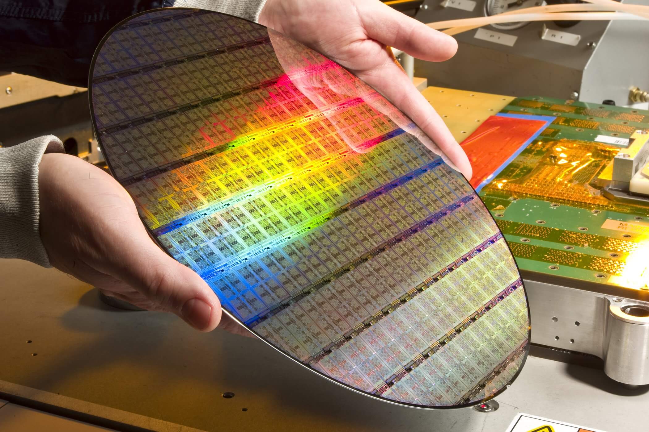
The fabrication process of a wafer before the chips are packaged. Photo Credit: Evan Lissoos
If we add a precisely controlled amount of electron donor elements like arsenic, antimony, or phosphorus, we can create an n-type region. Since the silicon area where these elements were applied now has an excess of electrons, it will become negatively charged. This is where the name n-type and the "n" in nMOS comes from. By adding electron acceptor elements like boron, indium, or gallium to the silicon, we can create a p-type region which is positively charged. This is where the "p" in p-type and pMOS come from. The specific processes to add these impurities to the silicon are known as Ion Implantation and Diffusion and they are bit beyond the scope of this article.
Now that we can control the electrical conductivity of certain parts of our silicon, we can combine the properties of multiple regions to create transistors. The transistors used in integrated circuits, known as MOSFETs (Metal Oxide Semiconductor Field Effect Transistors), have four connections. The current we are controlling flows through the Source and Drain. In an n-channel device it typically goes in the drain and out the source while in an p-channel device, it typically flows in the source and out the drain. The Gate is the switch used to turn the transistor on and off. Finally, the Body of the device isn't relevant to processor so we won't discuss it here.
The physical structure of an inverter in silicon. Each colored region has different conductivity properties. Note how the different silicon components correspond to the schematic on the right
The technical details of how transistors work and how the different regions interact is enough to fill a graduate level college course, so we'll just touch the basics. A good analogy for how they work is a drawbridge over a river. The cars, electrons in our transistor, would like to flow from one side of the river to the other, the source and drain of our transistor. Using an nMOS device as an example, when the gate is not charged, the drawbridge is up, the electrons can't flow across the channel. When we lower the drawbridge, we form a road over the river and the cars can move freely. The same thing happens in a transistor. Charging the gate forms a channel between the source and drain allowing current to flow.
To be able to precisely control where the different p and n regions of the silicon are, manufacturers like Intel and TSMC use a process called photolithography. This is an extremely complex multi-step process and companies spend billions of dollars perfecting it to be able to build smaller, faster, and more energy efficient transistors. Imagine a super-precise printer that can be used to draw the patterns for each region onto the silicon.
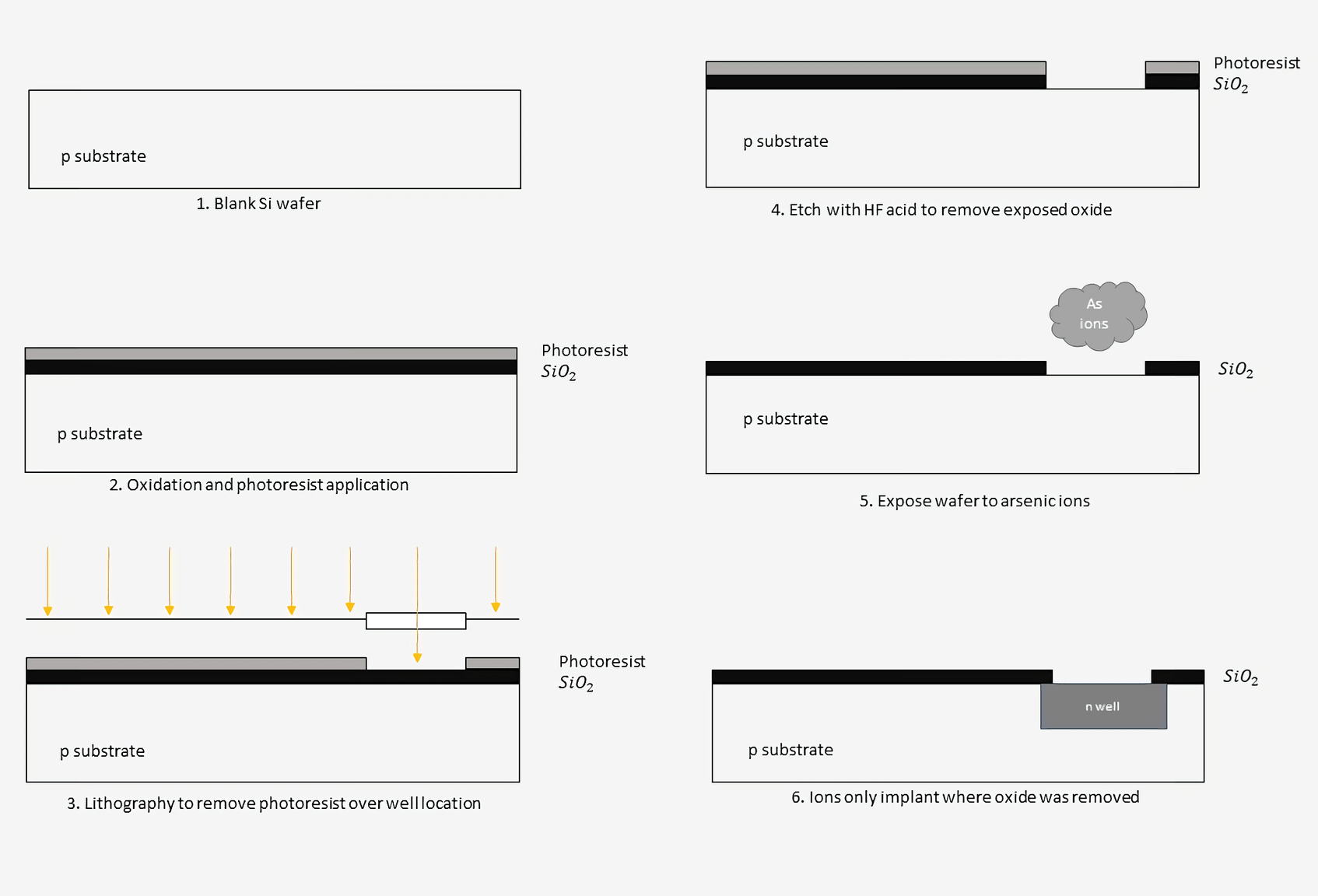
The process of building transistors into a chip starts with a pure silicon wafer. It is then heated in a furnace to grow a thin layer of silicon dioxide on the top of the wafer. A light-sensitive photoresist polymer is then applied over the silicon dioxide. By shining light at certain frequencies onto the photoresist, we can strip the photoresist in the areas we want to dope. This is the lithography step and is similar to how printers work to apply ink to certain areas of a page, just at a much smaller scale.
The wafer is etched with hydrofluoric acid to dissolve the silicon dioxide where the photoresist was removed. The photoresist is then removed, leaving behind just the oxide layer beneath. The doping ions can then be applied to the wafer and will only implant themselves where there are gaps in the oxide.
This process of masking, imaging, and doping is repeated dozens of times to slowly build up each feature level in a semiconductor. Once the base silicon level is done, metal connections will be fabricated on top to connect the different transistors together. We'll cover more about these connections and metal layers in a bit.
Of course, chip makers don't just do this process of making transistors one at a time. When a new chip is designed, they will generate masks for each step in the fabrication process. These masks will contain the locations of each element of the billions of transistors on a chip. Multiple chips are grouped together and fabricated at once on a single die.
Once a wafer is fabricated, the individual dies are sliced up and packaged. Depending on the size of a chip, each wafer may fit hundreds or more chips. Typically, the more powerful the chip being produced, the larger the die will be and the fewer chips the manufacturer will be able to get from each wafer.
It's easy to think that we should just make massive chips that are super powerful and with hundreds of cores, but that isn't possible. Currently, the single biggest factor preventing us from making bigger and bigger chips are defects in the manufacturing process. Modern chips have billions of transistors and if a single part of one is broken, the whole chip may need to be thrown away. As we increase the size of processors, the chance that a chip will be faulty increases.
The actual yields that companies get from their fabrication processes are closely held secrets, but anywhere from 70% to 90% is a good estimate. It is common for companies to over-engineer their chips with extra functionality since they know some parts won't work. For example, Intel may design an 8-core chip but only sell it as a 6-core chip since they estimate that one or two cores may be broken. Chips with an unusually low number of defects are usually set aside to be sold at a higher price in a process known as binning.
One of the biggest marketing terms associated with chip fabrication is the feature size. For example, Intel is working towards a 10nm process, AMD is using a 7nm process for some GPUs, and TSMC has started work on a 5nm process. What do all of these numbers mean though? Traditionally, the feature size represents the minimum width between the drain and source of a transistor. As technology has advanced, we've been able to shrink our transistors to be able to fit more and more on a single chip. As transistors get smaller, they also become faster and faster.
When looking at these numbers, it's important to note that some companies may base their process size on different dimensions than the standard width. This means that different sized processes from separate companies may actually result in the same sized transistor. On the other hand, not all transistors in a given process are the same size either. Designers may choose to make some transistors bigger than others based on certain trade offs. For a given design process, a smaller transistor will be faster since it takes less time to charge and discharge the gate. However, smaller transistors can only drive a very small number of outputs. If a certain piece if logic is going to drive something that requires a lot of power, such as an output pin, it will need to be made much bigger. These output transistors may be orders of magnitude larger than the internal logic transistors.
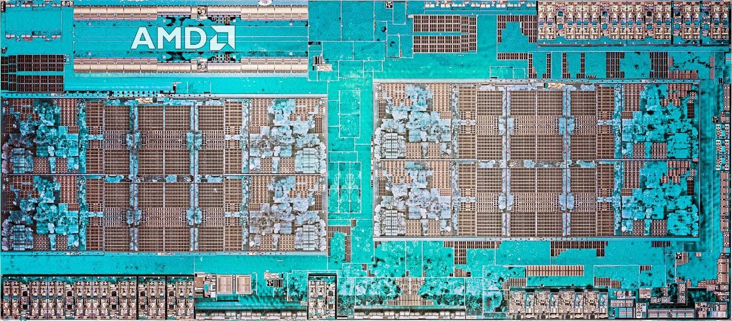
A die shot of a recent AMD Zen processor. Several billion transistors make up this design.
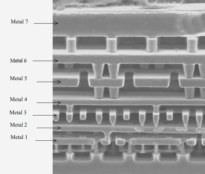
Designing and building the transistors is only half of the chip though. We need to build wires to connect everything according to the schematic. These connections are made using metal layers above the transistors. Imagine a multi-level highway interchange with on-ramps, off-ramps, and different roads crossing each other. That's exactly what is going on inside a chip, albeit on a much smaller scale. Different processes will have different numbers of metal interconnect layers above the transistors. As transistors get smaller, more metal layers are needed to be able to route all the signals. TMSC's upcoming 5nm process has a reported 15 metal layers. Imagine a 15-level vertical highway interchange and that will give you an understanding for just how complex the routing is inside a chip.
The microscope image below shows the lattice formed by seven metal layers. Each layer is flat and as they go higher, the layers get bigger to help reduce resistance. In between each layer are small metal cylinders known as vias that are used to jump up to a higher layer. Each layer typically alternates in direction from the one below it to help reduce unwanted capacitances. The odd metal layers may be used to make horizontal connections while the even layers may be used to make vertical connections.
As you can imagine, all these signals and metal layers get incredibly difficult to manage very quickly. To help solve this issue, computer programs are used to automatically place and route the transistors. Depending on how advanced the design is, programs can even translate functions in high-level C code down to the physical locations of every wire and transistor. Typically, chip makers will let computers generate most of the design automatically and then they will go through and optimize certain critical sections by hand.
When companies want to build a new chip, they will start their design with standard cells that the fabrication company provides. For example, Intel or TSMC will provide designers with basic parts like logic gates or memory cells. The designers can then combine these standard cells into whatever chip they want to build. They will then send the foundry, the place where the raw silicon is turned into functioning chips, the layouts of the chip's transistors and metal layers. These layouts are turned into masks which are used in the fabrication process we covered above. Next we'll see what this design process might look like for an extremely basic chip.
First we see the layout for an inverter which is a standard cell. The slashed green rectangle at the top is the pMOS transistor and the transparent green rectangle at the bottom is the nMOS transistor. The vertical red wire is the polysilicon gate, the blue areas are metal 1, and the purple areas are metal 2. The input A comes in on the left and the output Y goes out on the right. The power and ground connections are made at the top and bottom on metal 2.
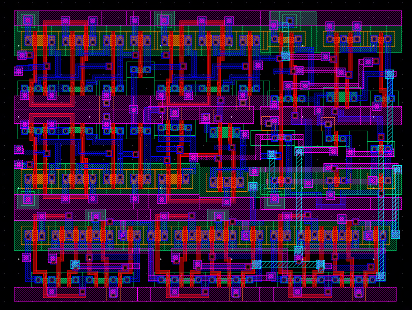
Combining several gates, here we have a basic 1-bit arithmetic unit. This design can add, subtract, and perform logical operations on two 1-bit inputs.The slashed blue wires that go vertically are metal 3 layers. The slightly larger squares on the ends of the wires are vias that connect two layers.
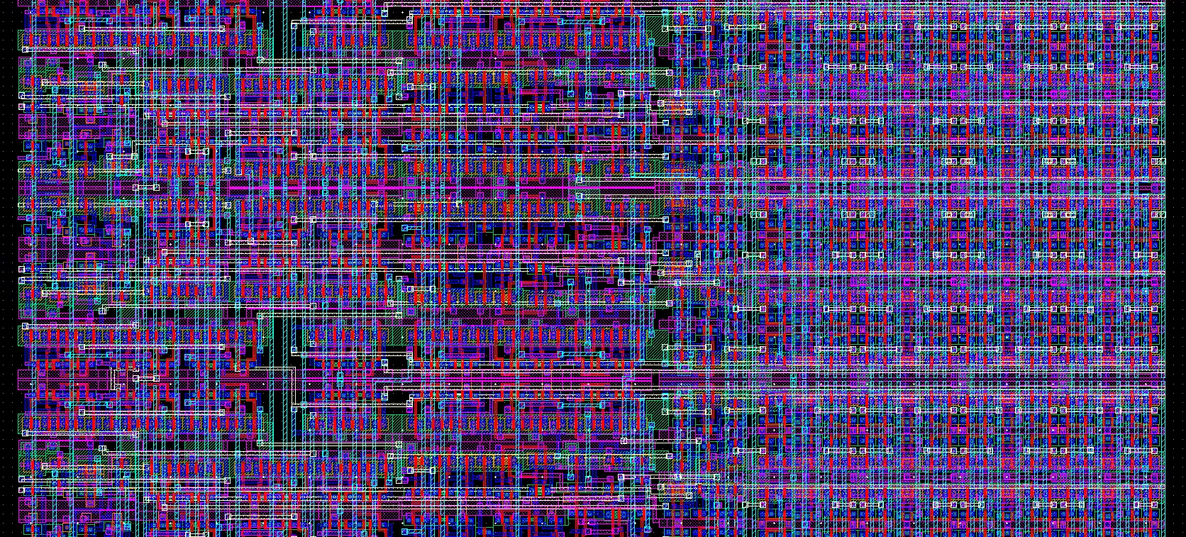
Finally, putting together many cells and about 2,000 transistors, we have a basic 4-bit processor with 8-bytes of RAM on four metal layers. Looking at how complex this is, one can only imagine the difficulty of designing a 64-bit CPU with megabytes of cache, multiple cores, and 20+ pipeline stages. Given that today's high-performance CPUs can have upwards of 5-10 billion transistors and a dozen metal layers, it is not an exaggeration to say that they are literally millions of times more complex than this.
This should give you an appreciation for why your new CPU was an expensive piece of tech or why it takes AMD and Intel so long in between product releases. It typically takes anywhere from 3 to 5 years for a new chip to go from the drawing board to the market. That means that today's fastest chips are made with several year old technology and that we won't see chips with today's state of the art fabrication technology for many years.
With that, we are all done with our deep dive into how processors are built.
In the fourth and last installment of the series we'll return from the physical domain and look at current trends in the industry. What are researchers working on now to make the next generation of computers even faster?
(instruction set architectures, caching, pipelines, hyperthreading)
Part 2: CPU Design Process
(schematics, transistors, logic gates, clocking)
Part 3: Laying Out and Physically Building the Chip
(VLSI and silicon fabrication)
Part 4: Current Trends and Future Hot Topics in Computer Architecture
(Sea of Accelerators, 3D integration, FPGAs, Near Memory Computing)
In the third part of the series we explored how the physics of how transistors work, how their individual components are built in silicon, and how they are connected to create useful circuits and chips.
Masthead credit: Semiconductor manufacturing image by Macro
